In this tutorial, we will learn about IP header protocol structure. We will see IPv4 header format, some questions based on it, etc.
In the previous tutorial, we started learning about the network layer. We studied about its main responsibilities and now from this tutorial onwards we get into the deeper section of the network layer. We begin this by knowing the various bits assigned to different function in this layer. The diagram which shows the bifurcation of bits is called IP header.
Let us look at the IP header before we move ahead to fragmentation. The numbers in the brackets are the total bits assigned for that part.

Notes –
- The options are variable. They may or may not be required sometime. Thus, the total frame length will be variable.
- Total length of a frame = 20 bytes to 60 bytes (20+40 bytes for options)
- Thus, minimum header length = 20 bytes
- Maximum header length = 60 bytes
- Version is used to decide IPv4 or IPv6 version.
- Identification number is used to identify the fragment in case of fragmentation. More fragment tells us that there are more fragments after a particular fragment. Do not fragment tells us that a particular fragment cannot be fragmented further.
- Fragment offset informs the number of data bytes ahead of a particular fragment a particular datagram.
Question. If maximum possible header length is 60 bytes then why does header length have only 4 bits assigned to it in the IP Header?
Ans.
With 4 bits, maximum possible number is 15. But minimum header size is 20 and maximum header size is 60. Therefore in worst case, we may have to put a number 60 in the header which can take only 15. Thus, it might create a problem.
Solution:
In order to solve this problem, a scaling factor of 60/15=4 is used i.e. by dividing the actual length of the header by 4 we can keep it within range.
Example:
Assume header length calculated is 20 Bytes. Then, according to the scaling factor we put 20/4=5 in the IP header‟s “Header Length‟ Field. The receiver on the other hand would multiply the header length filed size by 4 and get the actual length.
Question:
Given a number how do we identify if it is actual header length or header length field?
- Range of header length = 20 Bytes to 60 Bytes
- Range of header length field = 0 – 15 (out of them 0-4 is not a valid header length field size as minimum header length is 20 and thus minimum header length field size is 20/4=5). Thus actual range is 5-15.
- Since header length field cannot be a decimal number thus we use padding bits to make it an integer. Example: If the header length is 23 Bytes then we pad one byte dummy data and make it 24 bytes and put 24/4=6 in the header length field.
Time to live
Routing table exists for every router. It maintains an entry contain network ID and Subnet Mask each for every network it is connected to. It also has an entry for a default router. For every router one network is used as a default network.
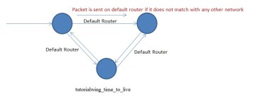
Thus, there could be a problem of infinity loop. Unnecessarily, bandwidth, buffers and processing time is wasted in this case. Over a period of time many packets would be circulating here, entire route would get busy, routers could become busy and important packets may get discarded since the routers can‟t handle them. Thus, time to live is introduces. We do not allow any station to take more than the defined no of hops. If take more than the number of hops we discard the packet.
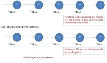
Destination accepts the packet if TTL>=0. If TTL=0 at a router, the router would discard the packet. Thus, the main purpose of time to live is to discard the packet that falls in infinity loop. Any device falling on the way during communication should decrease the time to live.
Header Checksum
Even though IP datagram header and data exist, header checksum is calculated only on header and not data. Header is divided into 16 parts equally i.e. 2B each and then every 2 bytes is interpreted as 1 and added i.e. 1‟s complement addition is performed and the negative of that number is put at checksum in the header checksum field.
Q. What is header checksum is not available?
Ans. We put all 0‟s in header checksum.
Q. What if the last byte remains after pairing every byte?
Ans. We use header size as multiple of 4. Every multiple of 4 is an even no. checksum can be counted easily by dividing an even no of bits into pairs of 2 bytes each. Thus, a pair of two bytes is added to other pairs.
Q. Why do we calculate header checksum on header only and not on data? Ans. Sender computes the header checksum. The packet is then transferred to a router. But every router makes at least one change in a packet i.e. decreases the TTL by 1 at every router. Thus, the header checksum calculated here will be with a different TTL, the checksum will change and every router will have to recalculate checksum. Thus if data is also included to calculated checksum, router will unnecessary waste a huge time as the data size is huge. Thus, we perform checksum only on data header and not on data.
Q. What are the field which might change at the router?
Ans. Time to Live, Fragment Offset, More fragment, total length, options, header length.
Options:
The possible options are:
- 1. Record route: The route through which the packet passes is recorded. Assume R1, R2, R3 are the different routers.

Limitation of record route: Maximum size of the options is only 40 bytes in the IP header. Since each IP Address is 4 bytes each, a maximum of ten routers can be recorded. Since some space is also required for “what is the type of option” in the IP header and some space is reserved to indicate the end of IP addresses thus a maximum of 9 addresses can be recorded for this option.
- 2. Source routing: A packet going out carries along the route on which it is going to travel in order to reach its destination. If a packet carries along it the entire path it is known as strict source S R1 R2 R3 D Route of R1 is recorded. Destination knows that the packet has travelled through routersR1, R2, R3. routing, the entire path is specified by the source in this case. If the packet carries along some part of its path or none of its path then the path is further decided by the routers on the way with the help of routing tables and thus it is called loose source routing. Destination IP address can be changed in case of loose source routing. Source routing is meant only for administration purpose practically and thus only as network administrator can use it.
- 3. Padding: Extra zeroes are added to see that header length size is an integer, this is called padding. If required it is mentioned in the options.
In this tutorial, we have studied about the IP header in the network layer. We now move on to study the details of fragmentation in the upcoming next tutorial.
You must be logged in to post a comment.